Master the Platform: Step-by-Step User Guide
Welcome to shadesail.design—the browser-native CAD and 3D visualization suite built specifically for custom shade sails. Whether you are an industry professional or a first-time designer, our platform takes your raw site dimensions and turns them into production templates with zero fuss.
Part 1: The "No-Fuss" Fast-Track (CAD in 60 Seconds)
If you just want to input your flat tape measurements and generate manufacturing files immediately without sorting through advanced controls, follow this streamlined path:
- Step 1: Set Workflow Units: Toggle between Millimeters or Inches at the top. The software logic updates automatically to prevent rounding errors.
- Step 2: Fabric & Color Selection: Select your shade cloth type—calibrated to real fabric physics like Gale Pacific—and select your colorway to instantly populate the visualizer.
- Step 3: Choose Your Corners: Select your target layout configuration, seamlessly supporting anywhere from a standard 3-point triangle up to a complex 8-point custom layout.
- Step 4: Punch In Dimensions: Input your straight tape measures between your posts moving in a strict clockwise direction (A to B, B to C, C to A, etc.) into the data fields.
- Step 5: Click "Generate Sail": Watch the live engine calculate the spatial paths in real-time, outputting an interactive 3D mesh model with safe default hardware tension gaps (350mm) and catenary curves already applied. Go straight to the export layout!
Part 2: The Sculptor’s Toolkit (Advanced Manipulation)
Once you feel comfortable with your baseline design, you can unleash the full power of our advanced parameters to customize the sail for difficult architectural sites:
Controlling the Z-Axis (Heights, Hypars & Slopes)
A tensioned sail should never be flat. Use our Smart Design Wizard to alternate high/low corners for an aerodynamic, twist-stabilized Hypar Twist saddle shape, or use the 20% Rain Slope wizard to ensure heavy downpours sheet away instead of pooling in the center pocket.
Custom Catenary Edge Curves
While the engine applies a safe structural inward arc to distribute perimeter tension evenly, you can override each side independently. Shallow the curve percentage to clear a tight roof fascia, or deepen a perimeter dip for custom aesthetic lines.
Engineering Gaps & Workshop Overlaps
Adjust individual corner hardware allowances down to the exact millimeter to match custom turnbuckle chains. You can also specify your workshop’s native production rules for outer hem turns (+50mm) and inner panel seam overlaps (+20mm).
Mastering Seam Layouts (8 Automated Modes)
Completely control fabric panel cuts based on raw roll constraints. Select Auto / Roll Width for raw yield optimization, Equal Panels to eliminate weak sliver-cuts at corner vertices, or Follow Hypar Twist to align sewing seams along natural torsional stress vectors.
Part 3: Presentations, Simulations & Professional Deliverables
Before passing files to the workshop, utilize our high-fidelity visualization layer to protect your margins and confirm site viability:
True 3D Seam Overlay: Show clients exactly how sewn lines look across a tensioned 3D curve surface before cutting fabric, clearing up structural expectations on the spot.
Live Sun & Shadow Simulator: Input precise coordinates, align the site compass with our North slider, and scrub through the day to watch shadows track across the property for any date.
The Three Pillars of Output: Export your final data packages split cleanly into a branded Customer Proposal (with 6-view cinematic camera paths and interactive 3D WebGL links), clean Pro CAD files mapping structural chords, and nested Fabrication Cutting Templates (.DXF) for plotting tables.
Part 4: Polytriangulation™ Measurement Diagrams
To feed our geometric solver accurately, you must provide absolute perimeter dimensions along with the correct structural cross-diagonals. Always survey lines of sight moving in a strict clockwise loop around the field posts.
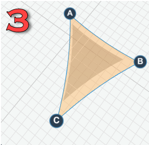
3-Point Triangular Matrix Layout
Required Structural Dimension Constraints:
- 3 Perimeter Edges: AB, BC, CA.
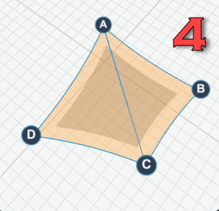
4-Point Quadrilateral Matrix Layout
Required Structural Dimension Constraints:
- 4 Perimeter Edges: AB, BC, CD, DA.
- 2 Internal Cross-Diagonals: AC, BD.
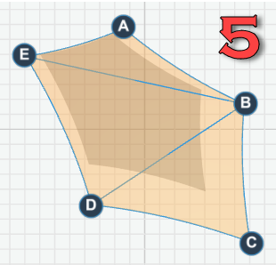
5-Point Pentagon Matrix Layout
Required Structural Dimension Constraints:
- 5 Perimeter Edges: AB, BC, CD, DE, EA.
- 5 Internal Cross-Diagonals: AC, AD, BD, BE, CE.

6-Point Hexagon Matrix Layout
Required Structural Dimension Constraints:
- 6 Perimeter Edges: AB, BC, CD, DE, EF, FA.
- 9 Internal Cross-Diagonals: AC, AD, AE, BD, BE, BF, CE, CF, DF.
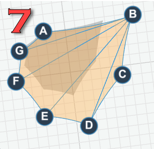
7-Point Complex Heptagon Layout
Required Structural Dimension Constraints:
- 7 Perimeter Edges: AB, BC, CD, DE, EF, FG, GA.
- 14 Internal Cross-Diagonals: AC, AD, AE, AF, BD, BE, BF, BG, CE, CF, CG, DF, DG, EG.
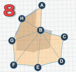
8-Point Custom Octagon Matrix Layout
Required Structural Dimension Constraints:
- 8 Perimeter Edges: AB, BC, CD, DE, EF, FG, GH, HA.
- 20 Internal Cross-Diagonals: AC, AD, AE, AF, AG, BD, BE, BF, BG, BH, CE, CF, CG, CH, DF, DG, DH, EG, EH, FG.